Loading...
Searching...
No Matches
Optimized High Speed Driver for nRF24L01(+) 2.4GHz Wireless Transceiver
Table of Contents
Design Goals
This library fork is designed to be...
- More compliant with the manufacturer specified operation of the chip, while allowing advanced users to work outside the recommended operation.
- Utilize the capabilities of the radio to their full potential via Arduino
- More reliable, responsive, bug-free and feature rich
- Easy for beginners to use, with well documented examples and features
- Consumed with a public interface that's similar to other Arduino standard libraries
News
See the releases' descriptions on the library's release page for a list of changes.
- Important
- There's going to be major changes in v2.0. As of v1.5, there is newer API that should be used instead of the deprecated API.
See our migration guide to understand what you should update in your code.
Useful References
Additional Information and Add-ons
- RF24Network: OSI Network Layer for multi-device communication. Create a home sensor network.
- RF24Mesh: Dynamic Mesh Layer for RF24Network
- RF24Ethernet: TCP/IP Radio Mesh Networking (shares Arduino Ethernet API)
- RF24Audio: Realtime Wireless Audio streaming
- nrf_to_nrf: OSI Layer 2 radio driver for NRF52x radios. Replaces RF24 layer for new radio devices.
- RF24G: Create a true mesh of up to 7 nrf24l01 and/or nrf52x devices
- TMRh20 Blog: RF24 Optimization Overview
- TMRh20: RPi/Linux with RF24Gateway
- All TMRh20 Documentation Main Page
More Information
- Project Blog: TMRh20.blogspot.com
- Maniacal Bits Blog
- Original Maniacbug RF24Network Blog Post
- ManiacBug on GitHub (Original Library Author)
- MySensors.org (User friendly sensor networks/IoT)
Platform Support Pages
- Arduino (Uno, Nano, Mega, Due, Galileo, etc)
- ATTiny
- Pico SDK support
- Linux Installation (or the alternative instructions using CMake), (Linux/RPi General, MRAA supported boards (Galileo, Edison, etc), LittleWire)
- Cross-compilation for linux devices
- Python wrapper available for Linux devices
General µC Pin layout
- See also
- also the individual board support pages for more info
Observe
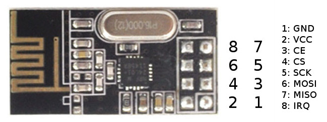
pinout.jpg
The table below shows how to connect the the pins of the NRF24L01(+) to different boards. CE and CSN are configurable.
| PIN | NRF24L01 | Arduino UNO | ATtiny25/45/85 [0] | ATtiny44/84 [1] | LittleWire [2] | RPI | RPi -P1 Connector |
|---|---|---|---|---|---|---|---|
| 1 | GND | GND | pin 4 | pin 14 | GND | rpi-gnd | (25) |
| 2 | VCC | 3.3V | pin 8 | pin 1 | regulator 3.3V required | rpi-3v3 | (17) |
| 3 | CE | digIO 7 | pin 2 | pin 12 | pin to 3.3V | rpi-gpio22 | (15) |
| 4 | CSN | digIO 8 | pin 3 | pin 11 | RESET | rpi-gpio8 | (24) |
| 5 | SCK | digIO 13 | pin 7 | pin 9 | SCK | rpi-sclk | (23) |
| 6 | MOSI | digIO 11 | pin 6 | pin 7 | MOSI | rpi-mosi | (19) |
| 7 | MISO | digIO 12 | pin 5 | pin 8 | MISO | rpi-miso | (21) |
| 8 | IRQ | - | - | - | - | - | - |
- [0] https://learn.sparkfun.com/tutorials/tiny-avr-programmer-hookup-guide/attiny85-use-hints
- [1] http://highlowtech.org/?p=1695 The ATTiny2313 is unsupported due to lack of sufficient memory resources.
- [2] http://littlewire.github.io/
Generated on for Optimized high speed nRF24L01+ driver class documentation by